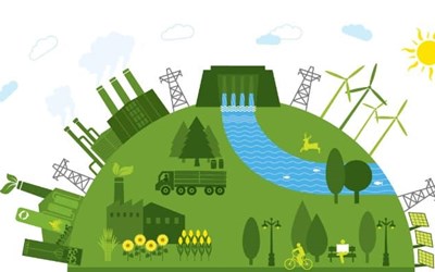
REVIEW POLIPAR SOLUTIONS FROM THE PRODUCTION OF ENERGY TO THE CONSUMPTION
Eklenme Tarihi 12.03.2019

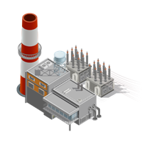
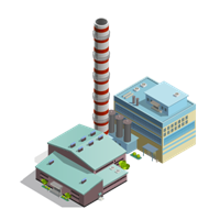
POWER STATIONS
A power station, also referred to as a power plant or powerhouse and sometimes generating station or generating plant, is an industrial facility for the generation of electric power. Most power stations contain one or more generators, a rotating machine that converts mechanical power into electrical power. The relative motion between a magnetic field and a conductor creates an electrical current. The energy source harnessed to turn the generator varies widely. Most power stations in the world burn fossil fuels such as coal, oil, and natural gas to generate electricity. Others use nuclear power, but there is an increasing use of cleaner renewable sources such as solar, wind, wave and hydroelectric.
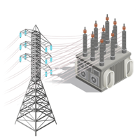
TRANSMISSION LINE
Electrical transmission is the process of delivering generated electricity - usually over long distances - to the distribution grid located in populated areas. An important part of this process includes transformers which are used to increase voltage levels to make long distance transmission feasible.
The electrical transmission system is used in combination with power plants, distribution systems, and sub-stations to form what is known as the electrical grid. The grid is designed to meet all of society's electricity needs, and is what gets the electrical power from its beginning to its end use. Since power plants are most often located outside of densely populated areas, the transmission system must be fairly large.
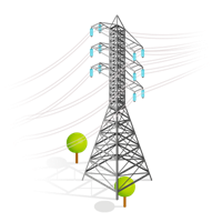
Power Lines
Power lines or transmission lines, are used to transport electricity from place to place. This electricity is in the form of alternating current and begins at step-up transformers, and typically span a distance of 500 kilometers or less. There are 3 types of lines:
Overhead lines are very high voltage, between 100 kV and 800 kV, and do the majority of long distance transmission. They must be high voltage in order to minimize power losses to resistance.
Underground lines are used to transport power through populated areas, underwater, or pretty much anywhere that overhead lines can't be used. They are less common than overhead lines due to heat-related losses and higher cost.
Subtransmission lines carry lower voltages (26 kV - 69 kV) to distribution stations, and can be overhead or undergroun
Electric power transmission is the bulk movement of electrical energy from a generating site, such as a power plant, to an electrical substation. The interconnected lines which facilitate this movement are known as a transmission network. This is distinct from the local wiring between high-voltage substations and customers, which is typically referred to as electric power distribution. The combined transmission and distribution network is known as the "power grid" in North America, or just "the grid". In the United Kingdom, India, Malaysia and New Zealand, the network is known as the "National Grid".
A wide area synchronous grid, also known as an "interconnection" in North America, directly connects a large number of generators delivering AC power with the same relative frequency to a large number of consumers. For example, there are four major interconnections in North America (the Western Interconnection, the Eastern Interconnection, the Quebec Interconnection and the Electric Reliability Council of Texas (ERCOT) grid). In Europe one large grid connects most of continental Europe.
Historically, transmission and distribution lines were owned by the same company, but starting in the 1990s, many countries have liberalized the regulation of the electricity market in ways that have led to the separation of the electricity transmission business from the distribution business.
Most transmission lines are high-voltage three-phase alternating current (AC), although single phase AC is sometimes used in railway electrification systems. High-voltage direct-current (HVDC) technology is used for greater efficiency over very long distances (typically hundreds of miles). HVDC technology is also used in submarine power cables (typically longer than 30 miles (50 km)), and in the interchange of power between grids that are not mutually synchronized. HVDC links are used to stabilize large power distribution networks where sudden new loads, or blackouts, in one part of a network can result in synchronization problems and cascading failures.
Electricity is transmitted at high voltages (115 kV or above) to reduce the energy loss which occurs in long-distance transmission. Power is usually transmitted through overhead power lines. Underground power transmission has a significantly higher installation cost and greater operational limitations, but reduced maintenance costs. Underground transmission is sometimes used in urban areas or environmentally sensitive locations.
A lack of electrical energy storage facilities in transmission systems leads to a key limitation. Electrical energy must be generated at the same rate at which it is consumed. A sophisticated control system is required to ensure that the power generation very closely matches the demand. If the demand for power exceeds supply, the imbalance can cause generation plant(s) and transmission equipment to automatically disconnect or shut down to prevent damage. In the worst case, this may lead to a cascading series of shut downs and a major regional blackout. Examples include the US Northeast blackouts of 1965, 1977, 2003, and major blackouts in other US regions in 1996 and 2011. Electric transmission networks are interconnected into regional, national, and even continent wide networks to reduce the risk of such a failure by providing multiple redundant, alternative routes for power to flow should such shut downs occur. Transmission companies determine the maximum reliable capacity of each line (ordinarily less than its physical or thermal limit) to ensure that spare capacity is available in the event of a failure in another part of the network.
igh-voltage overhead conductors are not covered by insulation. The conductor material is nearly always an aluminum alloy, made into several strands and possibly reinforced with steel strands. Copper was sometimes used for overhead transmission, but aluminum is lighter, yields only marginally reduced performance and costs much less. Overhead conductors are a commodity supplied by several companies worldwide. Improved conductor material and shapes are regularly used to allow increased capacity and modernize transmission circuits. Conductor sizes range from 12 mm2 (#6 American wire gauge) to 750 mm2 (1,590,000 circular mils area), with varying resistance and current-carrying capacity. For normal AC lines thicker wires would lead to a relatively small increase in capacity due to the skin effect (which causes most of the current to flow close to the surface of the wire). Because of this current limitation, multiple parallel cables (called bundle conductors) are used when higher capacity is needed. Bundle conductors are also used at high voltages to reduce energy loss caused by corona discharge.
Today, transmission-level voltages are usually considered to be 110 kV and above. Lower voltages, such as 66 kV and 33 kV, are usually considered subtransmission voltages, but are occasionally used on long lines with light loads. Voltages less than 33 kV are usually used for distribution. Voltages above 765 kV are considered extra high voltage and require different designs compared to equipment used at lower voltages.
Since overhead transmission wires depend on air for insulation, the design of these lines requires minimum clearances to be observed to maintain safety. Adverse weather conditions, such as high wind and low temperatures, can lead to power outages. Wind speeds as low as 23 knots (43 km/h) can permit conductors to encroach operating clearances, resulting in a flashover and loss of supply.[2] Oscillatory motion of the physical line can be termed gallop or flutter depending on the frequency and amplitude of oscillation.
Grid input
At the power stations, the power is produced at a relatively low voltage between about 2.3 kV and 30 kV, depending on the size of the unit. The generator terminal voltage is then stepped up by the power station transformer to a higher voltage (115 kV to 765 kV AC, varying by the transmission system and by the country) for transmission over long distances.
In the United States, power transmission is, variously, 230 kV to 500 kV, with less than 230 kV or more than 500 kV being local exceptions.
Losses
Transmitting electricity at high voltage reduces the fraction of energy lost to resistance, which varies depending on the specific conductors, the current flowing, and the length of the transmission line. For example, a 100 mi (160 km) span at 765 kV carrying 1000 MW of power can have losses of 1.1% to 0.5%. A 345 kV line carrying the same load across the same distance has losses of 4.2%.[23] For a given amount of power, a higher voltage reduces the current and thus the resistive losses in the conductor. For example, raising the voltage by a factor of 10 reduces the current by a corresponding factor of 10 and therefore the {\displaystyle I^{2}R} {\displaystyle I^{2}R} losses by a factor of 100, provided the same sized conductors are used in both cases. Even if the conductor size (cross-sectional area) is decreased ten-fold to match the lower current, the {\displaystyle I^{2}R} {\displaystyle I^{2}R} losses are still reduced ten-fold. Long-distance transmission is typically done with overhead lines at voltages of 115 to 1,200 kV. At extremely high voltages, more than 2,000 kV exists between conductor and ground, corona discharge losses are so large that they can offset the lower resistive losses in the line conductors. Measures to reduce corona losses include conductors having larger diameters; often hollow to save weight,[24] or bundles of two or more conductors.
Factors that affect the resistance, and thus loss, of conductors used in transmission and distribution lines include temperature, spiraling, and the skin effect. The resistance of a conductor increases with its temperature. Temperature changes in electric power lines can have a significant effect on power losses in the line. Spiraling, which refers to the way stranded conductors spiral about the center, also contributes to increases in conductor resistance. The skin effect causes the effective resistance of a conductor to increase at higher alternating current frequencies.
Transmission and distribution losses in the USA were estimated at 6.6% in 1997[25], 6.5% in 2007[25] and 5% from 2013 to 2019[26]. In general, losses are estimated from the discrepancy between power produced (as reported by power plants) and power sold to the end customers; the difference between what is produced and what is consumed constitute transmission and distribution losses, assuming no utility theft occurs.
As of 1980, the longest cost-effective distance for direct-current transmission was determined to be 7,000 kilometres (4,300 miles). For alternating current it was 4,000 kilometres (2,500 miles), though all transmission lines in use today are substantially shorter than this.[21]
In any alternating current transmission line, the inductance and capacitance of the conductors can be significant. Currents that flow solely in ‘reaction’ to these properties of the circuit, (which together with the resistance define the impedance) constitute reactive power flow, which transmits no ‘real’ power to the load. These reactive currents, however, are very real and cause extra heating losses in the transmission circuit. The ratio of 'real' power (transmitted to the load) to 'apparent' power (the product of a circuit's voltage and current, without reference to phase angle) is the power factor. As reactive current increases, the reactive power increases and the power factor decreases. For transmission systems with low power factor, losses are higher than for systems with high power factor. Utilities add capacitor banks, reactors and other components (such as phase-shifting transformers; static VAR compensators; and flexible AC transmission systems, FACTS) throughout the system help to compensate for the reactive power flow, reduce the losses in power transmission and stabilize system voltages. These measures are collectively called 'reactive support'.
Transposition
Current flowing through transmission lines induces a magnetic field that surrounds the lines of each phase and affects the inductance of the surrounding conductors of other phases. The mutual inductance of the conductors is partially dependent on the physical orientation of the lines with respect to each other. Three-phase power transmission lines are conventionally strung with phases separated on different vertical levels. The mutual inductance seen by a conductor of the phase in the middle of the other two phases will be different than the inductance seen by the conductors on the top or bottom. An imbalanced inductance among the three conductors is problematic because it may result in the middle line carrying a disproportionate amount of the total power transmitted. Similarly, an imbalanced load may occur if one line is consistently closest to the ground and operating at a lower impedance. Because of this phenomenon, conductors must be periodically transposed along the length of the transmission line so that each phase sees equal time in each relative position to balance out the mutual inductance seen by all three phases. To accomplish this, line position is swapped at specially designed transposition towers at regular intervals along the length of the transmission line in various transposition schemes.
Subtransmission
Subtransmission is part of an electric power transmission system that runs at relatively lower voltages. It is uneconomical to connect all distribution substations to the high main transmission voltage, because the equipment is larger and more expensive. Typically, only larger substations connect with this high voltage. It is stepped down and sent to smaller substations in towns and neighborhoods. Subtransmission circuits are usually arranged in loops so that a single line failure does not cut off service to a large number of customers for more than a short time. Loops can be "normally closed", where loss of one circuit should result in no interruption, or "normally open" where substations can switch to a backup supply. While subtransmission circuits are usually carried on overhead lines, in urban areas buried cable may be used. The lower-voltage subtransmission lines use less right-of-way and simpler structures; it is much more feasible to put them underground where needed. Higher-voltage lines require more space and are usually above-ground since putting them underground is very expensive.
There is no fixed cutoff between subtransmission and transmission, or subtransmission and distribution. The voltage ranges overlap somewhat. Voltages of 69 kV, 115 kV, and 138 kV are often used for subtransmission in North America. As power systems evolved, voltages formerly used for transmission were used for subtransmission, and subtransmission voltages became distribution voltages. Like transmission, subtransmission moves relatively large amounts of power, and like distribution, subtransmission covers an area instead of just point-to-point.[27]
Transmission grid exit
At the substations, transformers reduce the voltage to a lower level for distribution to commercial and residential users. This distribution is accomplished with a combination of sub-transmission (33 to 132 kV) and distribution (3.3 to 25 kV). Finally, at the point of use, the energy is transformed to low voltage (varying by country and customer requirements – see Mains electricity by country).
DISTRUBUTION LINES
is the final stage in the delivery of electric power; it carries electricity from the transmission system to individual consumers. Distribution substations connect to the transmission system and lower the transmission voltage to medium voltage ranging between 2 kV and 35 kV with the use of transformers.[1] Primary distribution lines carry this medium voltage power to distribution transformers located near the customer's premises. Distribution transformers again lower the voltage to the utilization voltage used by lighting, industrial equipment or household appliances. Often several customers are supplied from one transformer through secondary distribution lines. Commercial and residential customers are connected to the secondary distribution lines through service drops. Customers demanding a much larger amount of power may be connected directly to the primary distribution level or the subtransmission level.
Transmitting electricity a long distance at high voltage and then reducing it to a lower voltage for lighting became a recognized engineering roadblock to electric power distribution with many, not very satisfactory, solutions tested by lighting companies. The mid-1880s saw a breakthrough with the development of functional transformers that allowed the AC voltage to be "stepped up" to much higher transmission voltages and then dropped down to a lower end user voltage. With much cheaper transmission costs and the greater economies of scale of having large generating plants supply whole cities and regions, the use of AC spread rapidly.
In the US the competition between direct current and alternating current took a personal turn in the late 1880s in the form of a "War of Currents" when Thomas Edison started attacking George Westinghouse and his development of the first US AC transformer systems, pointing out all the deaths caused by high voltage AC systems over the years and claiming any AC system was inherently dangerous.[5] Edison's propaganda campaign was short lived with his company switching over to AC in 1892.
AC became the dominant form of transmission of power with innovations in Europe and the US in electric motor designs and the development of engineered universal systems allowing the large number of legacy systems to be connected to large AC grids.[6][7]
In the first half of the 20th century, in many places the electric power industry was vertically integrated, meaning that one company did generation, transmission, distribution, metering and billing. Starting in the 1970s and 1980s, nations began the process of deregulation and privatisation, leading to electricity markets. The distribution system would remain regulated, but generation, retail, and sometimes transmission systems were transformed into competitive markets.
A ground connection is normally provided for the customer's system as well as for the equipment owned by the utility. The purpose of connecting the customer's system to ground is to limit the voltage that may develop if high voltage conductors fall down onto lower-voltage conductors which are usually mounted lower to the ground, or if a failure occurs within a distribution transformer. Earthing systems can be TT, TN-S, TN-C-S or TN-C.
END USERS
End users included the classification of houses, shopping centers and industrial areas.
POLIPAR ensurer all stage of solutions from power generation to end users. For more informations please contact with us, polipar@polipar.com.tr